

Transcript
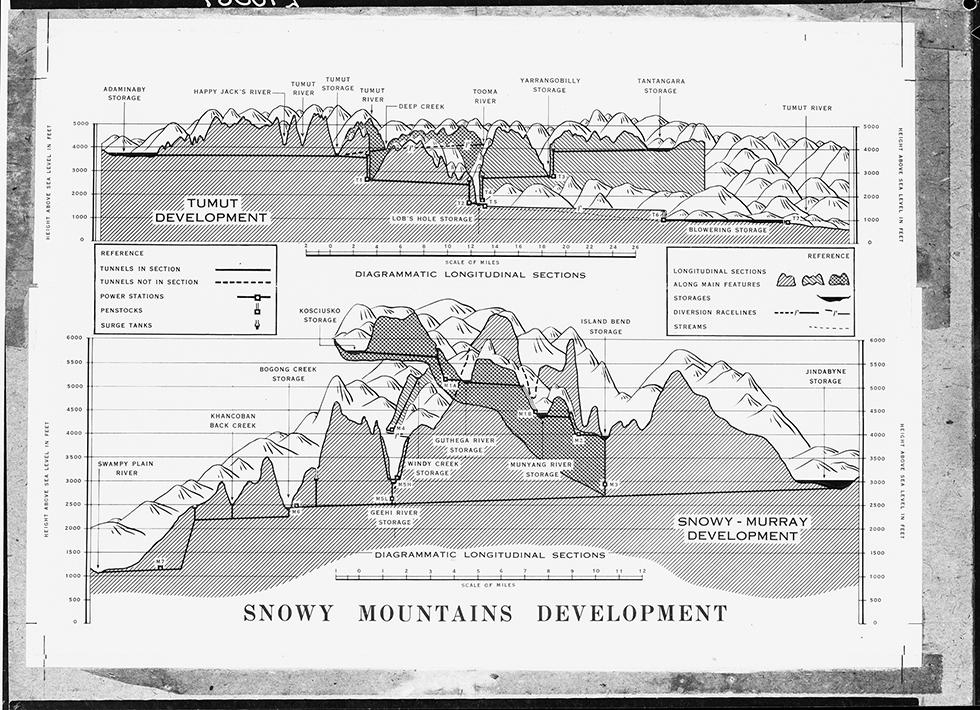
[A page with two cross-sectional diagrams of the Snowy Mountains Scheme. The title 'SNOWY MOUNTAINS DEVELOPMENT' is at the bottom of the page.]
[The two 'REFERENCE' boxes with the legend to the diagram list: 'TUNNELS IN SECTION', 'TUNNELS NOT IN SECTION', 'POWER STATIONS', 'PENSTOCKS', 'SURGE TANKS', 'LONGITUDINAL SECTIONS ALONG MAIN FEATURES', 'STORAGES', 'DIVERSION RACELINES', and 'STREAMS'.]
[The first diagram is labelled 'TUMUT DEVELOPMENT', 'DIAGRAMMATIC LONGITUDINAL SECTIONS'. According to the scale, the diagram shows a 64-mile section of the mountains, from 0 to 6000 feet above sea level. Tunnels descend across the mountains from their highest points at 'ADAMINABY STORAGE' and 'TANTANGARA STORAGE' at approximately 4000 feet above sea level, to the lowest point at 'BLOWERING STORAGE' approximately 1000 feet above sea level.]
[The following places are marked on the diagram, moving from left to right: 'ADAMINABY STORAGE', 'HAPPY JACK'S RIVER', 'TUMUT RIVER', 'TUMUT STORAGE', 'TUMUT RIVER', 'DEEP CREEK', 'LOB'S HOLE STORAGE', 'TOOMA RIVER', 'YARRANGOBILLY STORAGE', 'TANTANGARA STORAGE', 'BLOWERING STORAGE', and 'TUMUT RIVER'. There are also six power stations marked 'T1' to 'T6', and three marked diversion racelines.]
[The second diagram is labelled 'SNOWY – MURRAY DEVELOPMENT', 'DIAGRAMMATIC LONGITUDINAL SECTIONS'. According to the scale, the diagram shows a 33-mile section of the mountains, from 0 to 7000 feet above sea level. Tunnels descend across the mountains from the highest point at 'KOSCIUSKO STORAGE' at approximately 5700 feet above sea level, and a second point at 'JINDABYNE STORAGE', 3000 feet above sea level, down to the lowest point at 'SWAMPY PLAIN RIVER', 1000 feet above sea level.]
[The following places are marked on the diagram, moving from right to left: 'SWAMPY PLAIN RIVER', 'KHANCOBAN BACK CREEK', 'BOGONG CREEK STORAGE', 'KOSCIUSKO STORAGE, 'GEEHI RIVER', STORAGE', 'WINDY CREEK STORAGE', 'GUTHEGA RIVER STORAGE', 'MUNYANG RIVER STORAGE', 'ISLAND BEND STORAGE', and 'JINDABYNE STORAGE'. There are also nine power stations marked 'M1A', 'M1B', 'M2', 'M3', 'M4', 'M5H', 'M5L', 'M6', M7', and one marked diversion raceline.]
About this record
This is a schematic cross-section diagram of the Snowy Mountains hydro-electric scheme. It shows the two main sections of the scheme: the Tumut and the Snowy-Murray developments; the two transmountain tunnel systems that divert water from the Snowy River and its tributary, the Eucumbene River, to seven power stations (which generate electricity for New South Wales, Australian Capital Territory and Victoria) and then back into the Murray and Murrumbidgee rivers for irrigation in the Murray-Darling Basin; and storage areas (reservoirs).
Educational value
- Illustrates aspects of the Snowy Mountains Scheme – carried out between 1949 and 1974, the scheme was a major postwar construction project that was designed to meet Australia's increasing demand for power supplies and food production.
- Indicates the size of the scheme – it covers 3200 square kilometres, roughly the size of Switzerland.
- Is an early diagram of the scheme – some storage areas in the diagram, such as Kosciuszko, Windy Creek and Yarrangobilly, did not go ahead, while the Adaminaby storage area became Eucumbene Dam.
- Reveals the complexity of the scheme, which is ranked as one of the seven civil engineering wonders of the modern world – water is collected and stored behind dams in reservoirs and then diverted through tunnels and pipelines to power stations further down the mountain, where it generates electricity by turning hydro-electric turbines; the water is then released into the Murray and Murrumbidgee rivers for irrigation purposes.
- Details the Snowy–Tumut development – this diverts water from the Eucumbene and upper Murrumbidgee rivers to the Tumut Pond Reservoir and then into the Tooma and Tumut rivers; the waters then pass through a succession of power stations located in Tumut Gorge before being released via Blowering Dam back into the Tumut River and then into the Murrumbidgee River; this development generates electricity in the Tumut 1, Tumut 2, Tumut 3 and Blowering power stations and provides an average of 1380 gigalitres of water annually for irrigation.
- Details the Snowy–Murray development – this diverts water from the Snowy River to Island Bend Reservoir and then through a tunnel to Geehi Reservoir; from here, with water from the Geehi River, the water passes through the Murray 1 and Murray 2 power stations, before release via Khancoban Dam into Swampy Plain River (a tributary of the Murray); water collected in the Guthega River Reservoir generates electricity in the Guthega power station and is then released into Island Bend Reservoir; the development provides an average of 980 gigalitres of water annually.
- Shows that most of the Scheme's infrastructure is underground – only 2 per cent of the entire construction is visible above the ground.
- Details the expanse of the scheme's tunnel systems – the scheme includes 145 kilometres of interconnected transmountain tunnels and 80 kilometres of aqueducts.
- Shows 13 of the scheme's 16 major storage areas or reservoirs – the 16 reservoirs have a total storage capacity of 7000 gigalitres, which is 13 times the volume of Sydney Harbour.
- Indicates some of the engineering features of the scheme – these include the penstock (a water channel that leads from the wall of a reservoir to a turbine that generates electricity), surge tank (a concrete chamber that moderates surge pressures in the tunnel) and diversion raceline (an earth channel that directs water into aqueducts).
- Documents a project that reflected the ideals of industrial growth, modern design, and control of the environment that dominated policy making and the public imagination in postwar Australia.
Acknowledgments
Learning resource text © Education Services Australia Limited and the National Archives of Australia 2010.
Related themes
Need help with your research?
Learn how to interpret primary sources, use our collection and more.


